
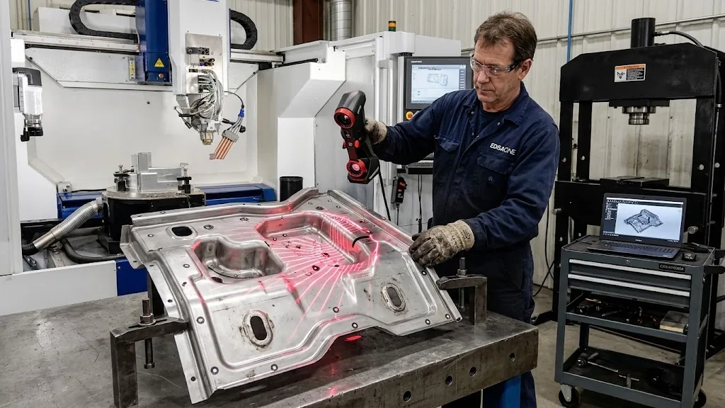
What is industrial 3D scanning and what is it used for?
Industrial 3D scanning captures the geometry of parts, components and tooling using optical measurement systems. It is used for digitising metal parts, quality control, dimensional inspection and reverse engineering. However, scanning a part does not automatically produce an editable CAD model: the deliverable depends on the goal of the project.
In industry, it is very common for a plant manager, design engineer or technical buyer to contact a metrology company asking for “3D scanning” without being entirely clear about which deliverable they need to solve their problem.
The customer often receives a point cloud or a triangular STL mesh with millions of polygons that their CAD software (SolidWorks, NX or Catia) cannot edit, open smoothly or turn into a manufacturing drawing. In other cases, they request full “reverse engineering” when their real goal was simply to certify whether a batch of parts meets drawing tolerances, incurring a 300% cost overrun in completely unnecessary modelling hours.
Although all three disciplines usually share the same physical capture tool (a metrology-grade laser or structured-light scanner), the subsequent engineering process, the deliverables and the technical objective are radically different. Choosing the wrong service leads to inflated quotes, weeks of delay and operational frustration. This guide defines precisely what each service provides and which one to commission depending on the industrial problem to be solved.
How does 3D scanning of industrial parts work?
3D scanning is the stage of massive optical data acquisition. Using laser triangulation or structured light fringe projection, the sensor digitises the surface of the physical object at millions of points per second, with metrology-grade resolution and accuracy (typically between ±0.015 mm and ±0.050 mm).
- What the deliverable is: A point cloud file (.asc, .xyz) or an optimised polygon mesh (.stl, .obj, .ply) made up of millions of tiny interconnected triangles.
- What it represents: It reflects the geometry of the physical part as built (as-built, as-cast or as-clad), including wear, warping, burrs, stamping defects and surface imperfections.
- Critical limitation: An STL file is neither a parametric model nor an editable B-Rep solid. It contains no perfect cylinders, infinite planes or feature tree; it is a hollow faceted shell that does not allow dimensions to be modified or standard 2D shop drawings to be generated.
- When to commission 3D scanning only:
- To keep an exact digital backup as a safeguard against breakage, loss or scrapping of old moulds and dies, freeing up space on the shop floor.
- For finite element analysis (FEA/CFD) directly on the real, deformed shape of the part.
- For virtual reality visualisation or for designing packaging and transport cradles that must fit the physical silhouette of the component.
3D scanning for dimensional inspection and quality control
Dimensional inspection by 3D scanning answers a contractual and quality question: “Does this physical part meet the tolerances of the nominal drawing?”
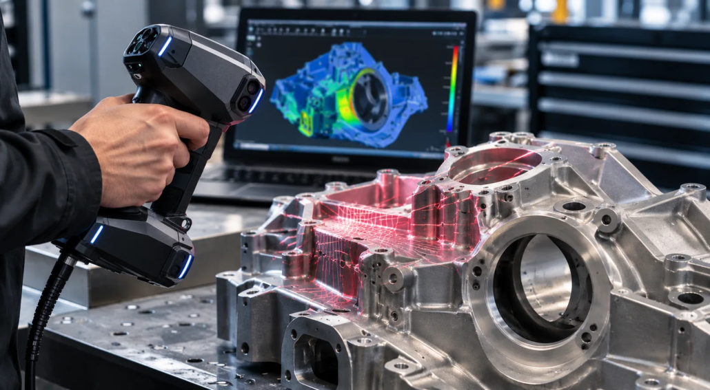
In this service, the scanned mesh of the real part is aligned in metrology software (such as Creaform 3D) with the customer’s original nominal CAD model using the part’s reference system and datums.
- What the deliverable is: A formal dimensional quality control report (PDF or interactive) including:
- Colour deviation map (colour map): A visual representation of the entire part surface where green indicates areas within tolerance, blue areas with missing material and red areas with excess thickness or warping.
- Geometric tolerance table (GD&T): Quantitative measurement of hole positions (⌖), flatness (◻), surface profiles (∩) and diameters against the lower and upper drawing limits.
- When to commission dimensional inspection:
- For first-article approvals (T1 samples, FAI reports or PPAP files for automotive).
- To analyse three-dimensional drawing deformation and springback in stamped sheet-metal parts.
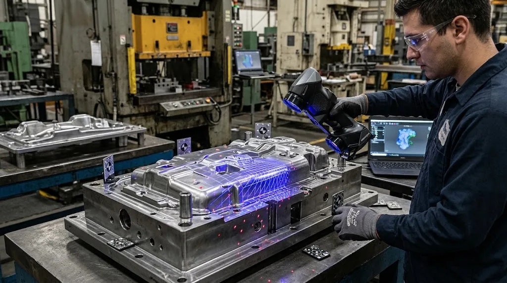
- For wear assessments of dies, moulds or cutting blades to decide whether the tool needs maintenance or LMD laser cladding.
3D scanning and reverse engineering: what are the differences?
Reverse engineering is an advanced reconstruction and CAD modelling process. It does not consist of automatically converting triangles into flat faces; it consists of interpreting the scan to deduce the original design intent of the engineer who conceived the part, abstracting away wear and manufacturing defects.
A metrology engineer fits mathematical planes to the flat faces of the mesh, identifies cylinders in the holes, models standard bend radii and recreates a clean, parametric mathematical solid.
- What the deliverable is: A standard solid CAD model in a neutral format (STEP, IGES, Parasolid x_t) or a native format with an editable feature tree (SolidWorks, Catia, NX), optionally accompanied by a dimensioned 2D manufacturing drawing.
- What it represents: The part in its ideal nominal state. Holes ovalised by wear become perfectly round and concentric again; faces deformed by bending return to exactly 90°.
- Levels of reverse engineering:
- Feature-based parametric modelling: The standard for machined or stamped mechanical parts; it allows extrusions to be edited, diameters to be changed and manufacturing drawings to be generated.
- NURBS surface fitting (freeform surfaces): Mathematical reconstruction of complex organic shapes (turbine blades, car body surfaces or mould cavities) with curvature continuity (G1/G2).
- When to commission reverse engineering:
- When a critical spare part must be made for a machine whose original manufacturer no longer exists and no drawings are available (legacy parts).
- To digitise manual modifications and adjustments that toolmakers made to the die by hand during press tryout and that were never recorded in the original CAD.
- To redesign an existing component with functional improvements or to adapt it to new production technologies.
3D scanning vs dimensional inspection vs reverse engineering: comparison
| Criterion | 3D scanning only | Dimensional inspection | Reverse engineering (Scan-to-CAD) |
|---|---|---|---|
| Key question | “What physical shape does it have?” | “Does it meet the nominal drawing?” | “How can I manufacture it again?” |
| Final deliverable | Polygon mesh (.STL / .OBJ) | Quality PDF report + colour map | 3D solid (.STEP / .SLDPRT) + 2D drawing |
| Nature of the model | Real geometry with wear (as-built) | Physical vs nominal comparison | Nominal mathematical geometry (as-designed) |
| CAD editability | None or very limited | Not applicable (quality document) | Full (B-Rep / parametric solid) |
| Relative cost | Base (1x) | Medium (1.5x to 2x) | High (3x to 5x, modelling-intensive) |
| Lead time | Hours / 1 day | 1 to 2 days | 3 to 7 working days |
Which 3D scanning service does your company need?
To avoid confusing quotes or useless deliverables, use this decision tree before requesting a quote:
- If you have the original 2D drawing or CAD file and need to verify manufactured parts:
- Request: Dimensional inspection by 3D scanning. Attach the PDF drawing with the critical-to-quality dimensions (CTQ) and the nominal 3D model.
- If you have NO drawings and need to have a broken or discontinued part manufactured:
- Request: Reverse engineering with a STEP deliverable and 2D drawing. Make clear to the supplier whether you need a perfect nominal model or whether the current wear must be reproduced.
- If you only need a volumetric envelope to check for interferences in a CAD assembly:
- Request: 3D scanning with a decimated STL mesh or simplified envelope (shrinkwrap). You will avoid paying for reverse engineering modelling hours.
- If you have physical tooling that has been modified by hand in the workshop:
- Request: 3D scanning + hybrid reverse engineering (CAD update). The modeller will only rebuild the faces that have physically changed compared with the base CAD.
Advantages of 3D scanning for industrial manufacturing
3D scanning makes it easier to document real geometries, compare parts with nominal models and recover information from tooling without drawings. Its value depends on the subsequent processing of the data and on the accuracy required in each project.
Conclusion: how to choose the right 3D digitisation service
A 3D scanner is a physical capture tool; what determines the success of the project is the engineering decision on how to process that information.
Commissioning full reverse engineering for a quality control problem, or requesting a basic STL scan expecting to modify it in SolidWorks or Catia, are common mistakes that eat up budgets and stall projects. Defining clearly whether your goal is to archive the shape, audit tolerances or rebuild a manufacturing drawing is the fundamental step to commissioning exactly the service your company needs.
3D scanning and reverse engineering with EDSAONE
At EDSAONE, together with MESHIND, we carry out 3D scanning and inspection for dimensional control and product development. Defining from the outset which deliverable each project needs makes it possible to choose the right service and avoid unnecessary costs.
Do you need to digitise, verify or rebuild a part? Contact the EDSAONE team to discuss your case and the most suitable deliverable.


