
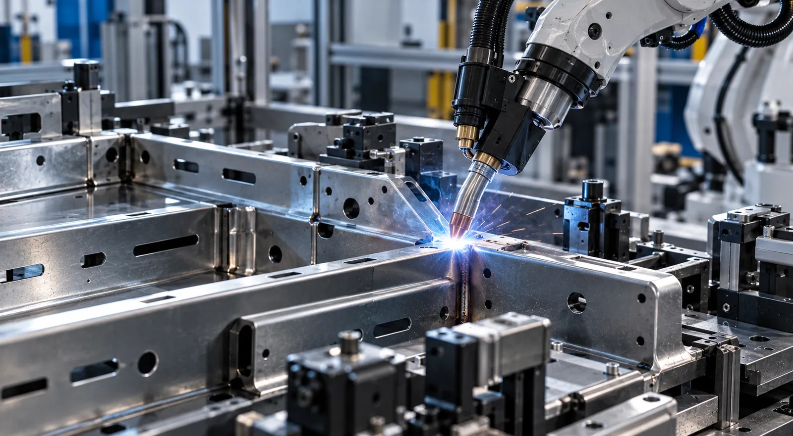
The design of a metal joint largely determines whether a sheet-metal assembly can be manufactured in an automated, repeatable and cost-effective way. Choosing a welding or assembly technology is not enough: joint geometry, part positioning, tool accessibility and tolerances all determine how well a robotic cell performs.
In this guide we explain five design for manufacturing and assembly (DFM/DFMA) principles, together with a comparison matrix and a checklist for preparing metal joints intended for series production.
Why metal joint design determines automation
In the series production of sheet-metal subassemblies and structural components, automating the joining process (with robotic MIG or laser welding cells, resistance welding stations or clinching presses) is often presented as the ultimate solution for cutting labour costs and multiplying output.
However, moving an assembly originally designed for manual welding or riveting into a robotic cell often ends in production failure. A human operator has sensory adaptability: if a sheet arrives slightly warped from the die or has an irregular 1.5 mm gap, they force it with a lever, adjust the clamp, tilt the torch or add more filler wire on the fly to save the joint.
An industrial robot, on the other hand, cannot improvise. It is an extraordinarily fast and repeatable machine (±0.05 mm), but completely blind and rigid: if the metal joint is not exactly at the programmed coordinate in 3D space, the arc will jump off the edge, burn through the sheet or leave a false weld without fusion.
From a Design for Manufacturing and Assembly (DFMA) perspective, automation is not about replacing the welder with a robotic arm; it is about redesigning part geometry so that the process is immune to variability. This guide sets out the essential design rules for metal joints conceived from the outset for robotic, unattended manufacturing.
Five principles for designing automated metal joints
To ensure that a metal assembly can be joined at high speed without line stoppages or rejects, the CAD model must incorporate five geometric principles:
Self-locating metal joint geometry (tab & slot)
In manual production, positioning depends on the operator measuring, aligning and clamping parts against stops. In an automated cell, robot cycle time is wasted if it depends on complex fixtures with dozens of pneumatic clamps that obstruct the path.
The DFMA solution: Incorporate tab-and-slot geometries, embossed dimples or self-centring chamfered flanges into the stamping or laser cutting.
Operational effect: The parts fit together like a construction kit in a single unambiguous position, by gravity or with light loading pressure. The welding fixture is drastically simplified, reduced to a basic quick-clamping support.
Repeatability and joint position tolerances
In robotic arc welding (MIG/MAG), the golden rule to avoid path deviations without resorting to costly vision systems or through-arc seam tracking is:
Δjoint position ≤ ±½ ∅wire
With standard 1.0 mm wire, the actual position of the joint groove must not vary by more than ±0.5 mm from the robot program.
To achieve this, the manufacturing datums of each stamped part must coincide with the support points of the robotic fixture. Do not dimension parts with cumulative dimension chains; link the faces forming the joint to a common primary datum pierced flat in the first station of the die.
Accessibility for torches, guns and tools
A recurring mistake in the engineering office is to check in CAD that the welding torch or spot-welding gun “touches” the joint line, forgetting to model the real head with its hoses, earth cables and gas nozzles:
- Conical safety envelope: Reserve a free approach corridor with a cone angle of at least 45° around the joint to allow optimal orientation of the welding nozzle relative to the weld pool.
- Avoid extreme wrist reorientation: Design joints so that the robot can complete several welds in a single continuous pass or in the same horizontal plane (+Z downwards), avoiding forced movements of axes 5 and 6 that slow the cycle and increase the risk of collision with the fixture.
Controlling metal joint gap and fit-up
A robot is not afraid of a fixed gap; what destroys the process is a variable gap:
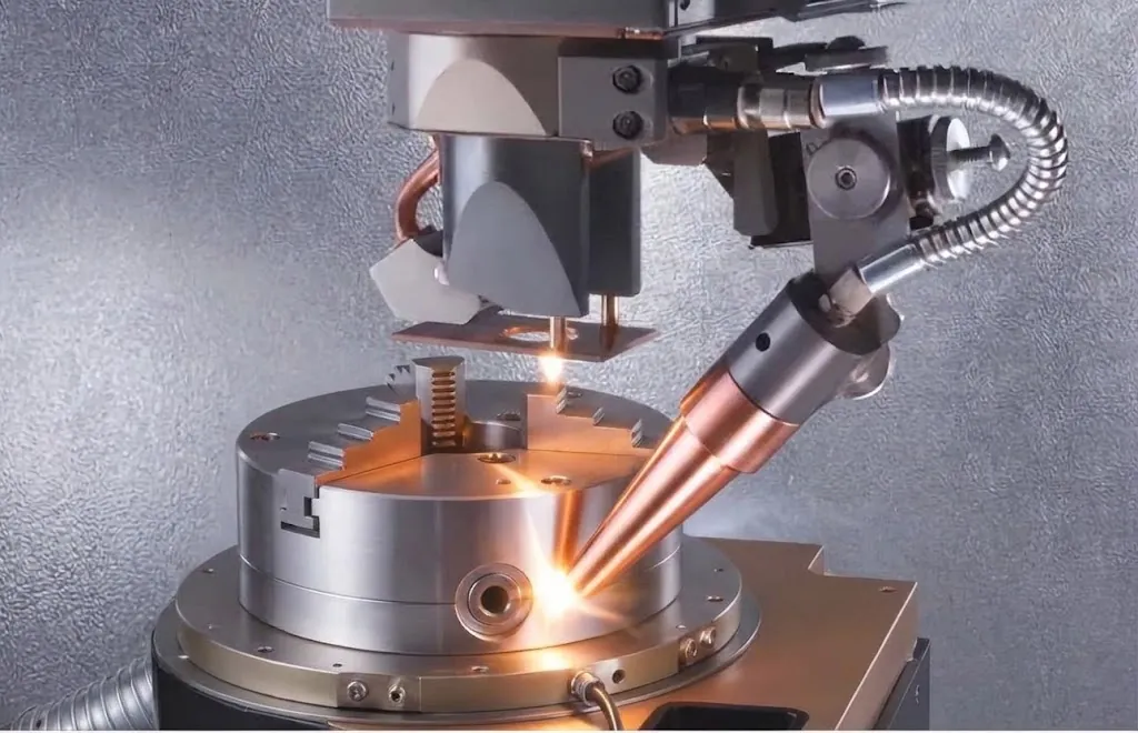
- In laser welding (LBW), the gap between sheets must be strictly below 0.10–0.15 mm and constant along the entire length. A local variation to 0.3 mm will cause instant burn-through (blow-through).
- In MIG-MAG welding, the robot can be programmed to bridge a 1.0 mm gap, but if the part varies from 0 mm to 1.5 mm along the seam due to bending inaccuracy, the weld pool will collapse.
The DFMA solution: Design lap joints or flange joints instead of pure butt joints. Lap joints dimensionally absorb variations from cutting and springback without opening the joint gap.
Thermal expansion and fixture design
During intensive welding, the structure absorbs heat and expands plastically:
If the assembly and its fixture are rigidly clamped at all ends against fixed stops, longitudinal expansion has nowhere to go and will buckle the sheet upwards, changing the contact-tip-to-work distance (stick-out) during the robot’s pass.
The DFMA solution: Define a 3-2-1 locating system with a fixed point and floating or slotted supports that allow thermal expansion in a controlled direction, so that the part returns to its nominal dimension on cooling without seizing the fixture.
Manual vs automated metal joint design: comparison table
| Geometric parameter | Conventional design (manual) | Design optimised for automation (robot) |
|---|---|---|
| Joint configuration | Straight butt joint (requires manual alignment) | Lap joint or joint with backing flange |
| Positioning between parts | Measuring with gauges and clamping with G-clamps | Self-centring tab and slot |
| Joint accessibility | Tight angles overcome by welder skill | Unobstructed 45° conical corridor |
| Poka-yoke (error proofing) | Relies on the operator’s visual attention | Physical asymmetries that prevent reversed assembly |
| Expansion management | Manual straightening with press or torch after welding | Guided compliant fixturing that absorbs expansion |
| Weld type | Long continuous perimeter welds | Optimised stitch welds or clinching |
Virtual simulation of the metal joint before manufacturing
In modern design for automation, the drawing should not be released to purchasing or toolmaking without first going through an offline programming (OLP) simulation in 3D software (such as RobotStudio, DELMIA or Process Simulate):
- Reachability analysis: Checking that the robot reaches the start and end of each weld without hitting its axis travel limits or entering mathematical singularities.
- Collision detection: Dynamic simulation of torch movement together with the fixture clamps during rapid approach transitions.
- Cycle time optimisation: Re-sequencing welds so that the robot minimises non-productive air moves.
DFMA checklist for designing an automated metal joint
Before freezing the design of a subassembly intended for robotic manufacturing, check:
- Do the parts include tabs, slots or dimples that allow the assembly to be pre-fitted in a single unambiguous position?
- Is the physical joint guaranteed to repeat its position within a tolerance of less than half the welding wire diameter (±0.5 mm)?
- Is there a free space of at least 45° around the path to avoid collisions with the gas nozzle or gun?
- Have critical butt joints been replaced by lap joints that absorb cutting variations and upstream tolerances?
- Does the part have asymmetric features (poka-yoke) that prevent a loading robot from handling it the wrong way round?
How to improve series production through metal joint design
The profitability of a robotic welding or assembly cell is not decided at the robot’s control panel, but on the design engineer’s CAD screen.
Forcing automation onto an assembly conceived with a manual mindset inevitably leads to line stoppages due to arc start failures, collisions with fixtures and scrapped parts. Conversely, when parts are designed with self-locating or self-fixturing features, clear access and joints tolerant of variation, the robot works at full capacity: very fast cycles, consistent metallurgical quality and the most competitive unit cost on the market.
Metal joint design for industrial projects at EDSAONE
The choice of joining solution should be addressed from the design phase of the component and the production process. At EDSAONE, manufacturability analysis can help identify geometric constraints, tolerances and industrialisation requirements before defining the manufacturing strategy.
Do you have a metal assembly you want to automate? Share the drawing or CAD model and your production requirements so we can study the technical feasibility of the design.


